Friday, May 8, 2020

NetApp ONTAP 9.7 NVMe Configuration and Management

What is NVMe?


NVM Express (NVMe) is a data storage protocol that delivers the fastest response times for business-critical enterprise applications. However, NVMe is more than a storage specification; the broader NVMe over Fabrics protocol encompasses the entire data path, from server to network to storage system.

NVMe—the NVM Express data storage standard—is emerging as a core technology for enterprises that are building new storage infrastructures or upgrading to modern ones.
NVMe is both a protocol optimized for solid-state storage devices, and a set of open-source architectural standards for NVMEM components and systems.

NVMe adds some new names for some common structures.


An NVMe Qualified Name (NQN) identifies an endpoint and is similar to an iSCSI Qualified Name (IQN) in both format (domain registration date, domain registered, and something unique like a serial number). A namespace is analogous to a LUN (Logical Unit Number, a unique identifier for a logical or physical device); both represent an array of blocks presented to an initiator. A subsystem is analogous to an initiator group (igroup) (subsystems have considerably more functionality but for our purposes, we are focusing on how to map LUNs/namespaces), it is used to mask an initiator so that it can see and mount a LUN or namespace. Asymmetric Namespace Access (ANA) is a new protocol feature for monitoring and communicating path states to the host operating system’s Multipath I/O (MPIO) or multipath stack, which uses information communicated through ANA to select and manage multiple paths between the initiator and target.

NVMe will become an essential part of the modern data center, because it addresses three crucial attributes of data storage performance: IOPS, throughput, and latency.

The IOPS and bandwidth improvements are primarily the result of NVMe’s flexibility and its ability to take advantage of fast transport technologies to move NVMe commands and data.

These transports include:
                     FCP. Currently available in speeds of 16 and 32Gbps and soon 64Gbps.
                     RDMA Protocol.
Data center fast Ethernet: Currently available in 25, 40, 50, and 100Gbps.
InfiniBand: currently available with speeds up to 100Gbps.
                     PCI Express 3.0. Supports 8 gigatransfers per second (GT/s), which translates to approximately 6.4Gbps.

NVMe accelerates many of today’s most important emergent business workloads:

Artificial intelligence (AI).

Machine learning (ML)/deep learning (DL).

Internet of Things (IoT).

NVMe as a Storage Attachment Architecture

NVMe is most commonly used today for attaching disks and disk shelves. Many storage vendors and suppliers have introduced offerings based on using NVMe as a storage-attachment architecture and standard. Technically, in most cases, NVMe is the protocol used to perform I/O, whereas the physical transport is primarily PCIe.
In this scenario, NVMe replaces the SCSI command set with the NVMe command set and frequently replaces SATA or serial-attached SCSI (SAS) with PCIe to connect drives to the storage controller. NVMe relies on a physical attachment and transport. It uses PCIe as the transport.

NVMe-attached flash offers more bandwidth and reduced latencies because:
                     It offers more and much deeper queues: 64k (65,535) queues, each with a queue depth of 64k.
                     The NVMe command set is streamlined and therefore more efficient than legacy SCSI command sets.


Create a dedicated NVMe protocol supported SVM.


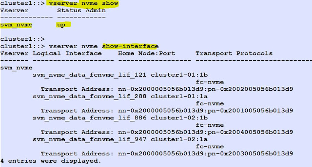
List the SVM details.


Check and List the NVMe/FC adapters.


Create NVMe LIF's.


List the NVMe Interfaces with their transport address.


Create a subsystem.


Get the host nqn (In linux host server:# cat /etc/nvme/hostnqn) & add the host nqn to subsystem.


Create a Namespace (like LUN).


Then Map the Namespace to the subsystem.


You can view the namespaces in ONTAP System Manager.


 You can view NVMe Namespaces  health and Performance in ActiveIQ Unified Manager.


Statistics view in sysstat command.


 To list the enabled NVMe feature and Max. Nmaespace size. 


Host Side Commands: (Linux Server)


To list the host nqn value.

# cat /etc/nvme/hostnqn

Check nvme-cli RPM or else install the RPM.

rpm -qa|grep nvme-cli
nvme-cli-1.6-1.el7.x86_64

To discover the namespaces (Devices).

nvme connect-all --transport=fc --traddr=nn-0x200a00a098c80f09:pn-0x200b00a098c80f09 --host-traddr=nn-0x20000090fae0ec9d:pn-0x10000090fae0ec9d

 List the connected nvme devices.

nvme list

Thursday, April 30, 2020

Three-Site Data Center Data Protection using NetApp ONTAP 9.7 SnapMirror


In today’s constantly connected global business environment, companies expect rapid recovery of critical application data with zero data loss. Organizations devise effective disaster recovery plans by keeping the below requirements in mind:

• Data should be recoverable in the event of catastrophic failure at one or more data centers (disaster recovery).
• Data should be replicated and distributed in an optimal way, taking into consideration major business criteria such as cost of storage, protection level against site failures, and so on.
• What needs to be protected and for how long should be driven by:
Shrinking recovery point objective (RPO), to achieve zero data loss
     Near-zero recovery time objective (RTO), for faster recovery of business-critical applications in case of disaster

Three-Site Data Center Topology
The three-site data center configuration can be done in either fan-out or cascade topology.

Fan-out Topology
Fan-out topology consists of primary and near disaster recovery data centers within region sites (with replication network having <10ms round trip time), will synchronously replicate data between themselves to achieve zero RPO. And the primary asynchronously replicates data on a regular basis depending on the quantity of new data being generated to the remote or far disaster recovery out-of-region data center. If disaster strikes the primary site, the application can be started with zero data loss from the near disaster recovery data center, which would also take over asynchronous replication to the far disaster recovery data center.


Steps to Configure Fan-out Topology:

Create intercluster role Lif's and configure cluster peer and SVM peer.

Check the cluster peer and vserver peer in all the 3 site NetApp Clusters.

Cluster1  --- peered with cluster2 and cluster3


Cluster2 peered with cluster1 and cluster3.


Cluster3 is peered with cluster1 and cluster2.


In cluster1, create a new source volume (Ex- volnew). (Primary Site)


In cluster2, create a destination volume with DP type. (Near DR Site)


In cluster2, create SnapMirror  (SM-S) Sync relationship. 


Then initialize the Snapmirror relationship, once the base line transfer is successful, the status will be Insync.


In Cluster3, (Far DR Site) create a DP volume and create a Async SnapMirror relationship between Primary Site and Far DR site.


Initialize the SnapMirror Relationship.


Primary Site to Near  DR Site (Sync) 


Primary Site to Far DR Site (Async).


Cascade Topology

Cascade topology is where the primary would synchronously replicate to the near disaster recovery site, and the near disaster recovery site would asynchronously replicate data to the far disaster recovery site. In case the near disaster recovery site goes down, you can configure an asynchronous replication directly to the far disaster recovery site over longer distance to ensure all the delta updates are being updated or replicated.


In Cluster1(Primary Site), Create a source volume to replicate.


In Cluster2 (Near DR Site) , Create a DP volume.


In Cluster2, create a SnapMirror Sync relationship between these two volumes.


In Cluster3(Far DR Site), create a DP volume.


In cluster3, create a Snapmirror (Async) between cluster2 and Clster3 volumes.


Wednesday, April 29, 2020

NetApp ONTAP 9.7 - Converting FlexVol volumes to FlexGroup volumes


FlexGroup Volume:

A FlexGroup volume is a scale-out NAS container that provides high performance along with automatic load distribution and scalability. A FlexGroup volume contains several constituents that automatically and transparently share the traffic.

If you want to expand a FlexVol volume beyond its space limit, you can convert the FlexVol volume to a FlexGroup volume. Starting with ONTAP 9.7, you can convert standalone FlexVol volumes or FlexVol volumes that are in a SnapMirror relationship to FlexGroup volumes.

Starting with ONTAP 9.7, you can perform an in-place conversion of a FlexVol volume to a FlexGroup volume without requiring a data copy or additional disk space.


To convert a FlexVol volume SnapMirror relationship to a FlexGroup volume SnapMirror relationship in ONTAP, you must first convert the destination FlexVol volume followed by the source FlexVol volume.


1. Create a new source flexvol volume (Ex- Volfg2) in cluster1. Check the volume style.


2.Mount the Flexvol in Linux Server and create files.


3. Create a destination flexvol volume (Ex- volfg2_dr) with DP type  in cluster2.


4. In cluster2, Create a snapmirror relationship.

Source : Cluster1  Vserver : svm_src1   Volume: volfg2
Target  : Cluster2  vserver : svm_dst1    volume : volfg2_dr


5. Initialize the snapmirror relationship.


6. To convert Flexvol to flexgroup, first quiesce the relationship.


7.Now verify the conversion process (-check-only option). Rectify if you will get any error.


8. Start the volume conversion in cluster2 (Snapmirror Destination volume).


9. Check the destination volume volume style. It changed to flexgroup.


10. Now convert the source volume in cluster1. (source volume - volfg2)


11. Successfully converted to flexgroup.


12. Then, in Cluster2 resync the snapmirror relationship.


Important: You cannot convert a FlexGroup volume back to a FlexVol volume.