NetApp ONTAP 9.8 software supports the Amazon Simple Storage
Service (S3). ONTAP supports a subset of AWS S3 API actions and allows data to
be represented as objects in ONTAP-based systems, including AFF, FAS, and ONTAP
Select.
The primary purpose of S3 in ONTAP is to provide support for
objects on ONTAP-based systems. The ONTAP unified storage architecture now
supports files (NFS and SMB), blocks (FC and iSCSI), and objects (S3).
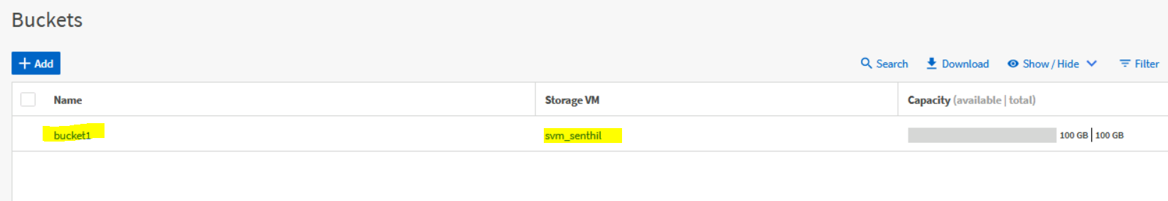
Architecture Object storage is an architecture that manages
data as objects, as opposed to other storage architectures such as file or
block storage. Objects are kept inside a single container (such as a bucket)
and are not nested as files inside a directory inside other directories.

Requirements
Platforms
•
• NetApp AFF storage system. S3 is supported on all AFF
platforms using ONTAP 9.8+.
•
• FAS storage system. S3 is supported on all FAS platforms
using ONTAP 9.8+.
•
• NetApp ONTAP Select. S3 is supported on all platforms
using ONTAP Select 9.8+.
•
• Cloud Volumes ONTAP. S3 is not supported on Cloud Volumes
ONTAP.
Data LIFs
Storage virtual machines (SVMs)
hosting object store servers require data LIFs to communicate with client
applications using S3. When configured for remote cluster tiering, FabricPool
is the client and the object store is the server.
Cluster LIFs
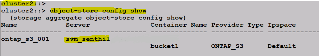
When
configured for local cluster tiering, a local tier (also known as a storage
aggregate in the ONTAP CLI) is attached to a local bucket. FabricPool uses
cluster LIFs for intracluster traffic.